


Framed or unframed, desk size to sofa size, printed by us in Arizona and Alabama since 2007. Explore now.
Shorpy is funded by you. Patreon contributors get an ad-free experience.
Learn more.


- Baldwin 62303
- Baldwin VO-1000
- Cold
- No expense spared
- Tough Guys
- Lost in Toyland
- And without gloves
- If I were a blindfolded time traveler
- Smoke Consumer Also Cooks
- Oh that stove!
- Possibly still there?
- What?!?
- $100 Reward
- Freeze Frame
- Texas Flyer wanted
- Just a Year Too Soon
- WWII -- Replacing men with women at the railroad crossing.
- Yes, Icing
- You kids drive me nuts!
- NOT An Easy Job
- I wonder
- Just add window boxes
- Icing Platform?
- Indiana Harbor Belt abides
- Freezing haze
- Corrections (for those who care)
- C&NW at Nelson
- Fallen Flags
- A dangerous job made worse
- Water Stop

Photos submitted by Shorpy members!
Print Emporium
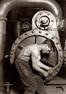


The Squeaky Wheel: 1904

Circa 1904. "Michigan Central Railroad engineer oiling up before the start." 8x10 inch dry plate glass negative, Detroit Publishing Company. View full size.
I Slipped Up!
I erred!
I see there is another photo of the Engineer oiling around!
The locomotive has a 4-wheel lead or pony truck! and the front truck DOES have brakes.
My mistake.
In the view showing the front truck, the Engineer has the spout in the hole in the crosshead oiling the wrist pin inside.
The crosshead sliding between its guides is part of the method of changing the reciprocating motion of the piston and piston rod inside the cylinder to rotary motion at the crank pins and wheels.
Similar to the change of motion of the piston and the crankshaft in an automobile engine.
As the fuel on a locomotive, ship or factory steam engine is burned in a firebox and heats water to steam externally from the piston and cylinder, a steam engine is known as an External Combustion Engine.
In a motor vehicle or a Diesel engine, the fuel is burned within the cylinder = an Internal Combustion Engine.
Slippery Sam.
The Engineer has the long spout of his oil can, or "feeder," stuck between the rear driving wheel spokes probably oiling the brass/bronze hub liner which is a bearing facing outward and it is designed to bear against the inside surface of the rotating driving wheel.
The locomotive driving axle bearings, one on each side of each axle, sit atop the polished steel bearing surfaces of the steel axles connecting the two driving wheels on each axle, one on each side of the engine.
In this case there are four driving wheels, two axles, four driving axle bearings.
The large leaf springs visible between the spokes carry some of the weight of the engine and press down on the top of the driving axle boxes and their bearings on the top of the axles.
The large many-leafed driving wheel springs, their linkages and their pivot-points are designed to equalize the locomotive weight so each axle and wheels carry a fair part of the load above for traction and so no one wheel set is too heavy for the track and structure below.
So the locomotive can go around curves and accept track irregularities, there is play in the axles inside the bearings so the locomotive slides back and forth atop the axles.
The inner-surfaces of the rotating wheels hit the stationary hub bearing facing outward, requiring lubrication. The axle boxes ride up and down in large jaws whose surfaces require lubrication.
Going forward, the driving axles and bearing boxes push against the forward jaw member by the steam and the pistons in their cylinders move the main and connecting rods and their crank pins rotate the driving wheels, forcing the frame, engine and tender and the train down the track.
The oiler spout would be used to apply required lubrication to all surfaces rubbing together to control wear.
Behind the Engineer can be seen the spoked trailing wheel and its truck which supports the rear end of the locomotive. This truck has its own external leaf springs and external axle box with bearing inside the hinged spring cover.
The axle box rides up and down in its jaws. The whole truck swivels back and forth on the track on curves.
The small hose and pipe plumbed into the front of the axle box is for cooling water if the bearing runs hot on the road, a hot box, so the engine can be kept moving rather than seize on the track and cause delays, or letting the axle end burn off thru friction, causing a derailment.
The large pipe and curved hose behind the axle box is to bring cold water from the tank in the tender up into the cab where a steam-operated injector will be used to force the water into the boiler for steam.
One pipe and injector on each side.
The large horizontal tank suspended under the cab is the second of two main air reservoirs which contain compressed air brought thru the pipe in its front center from the steam air pump and tank No. 1 on the left side of the engine.
The compressed air would be used for locomotive and train air brakes and to apply sand to the rails for traction.
The smaller air tank ahead is the Equalizing Reservoir used when setting the air brakes on the train as the Engineer reduces or raises air pressure therein with his train brake valve.
He can apply the engine and train brakes with the train brake valve, or apply and release just the engine brake alone from the separate engine brake valve.
If he wants just the train's brakes set, he can bail off his engine brakes to keep the locomotive wheels from sliding and their shrunk-on tires cool.
The front driving wheel brake shoe can be seen pressed against its wheel between the drivers.
The two-wheel front and rear trucks on this locomotive would not have brakes at all.
The front and rear drivers are counter-balanced to oppose the force of rotating weights of their main and connecting rods on the crank pins.
The rear wheel crank pins on this engine carry two rods, thusly requiring a larger counterweight, one on each side.
The Engineer's left hip is against the larger rear counterweight.
The lighter counterweight on the front wheel is inside the rim opposite the brake shoe.
Generally, the right crank pin leads the left crank pin going forward by 90 degrees on a 2-cylinder engine.
In this case the right crank pins are on front dead center, the piston all the way forward in its cylinder.
The left side crank pins would be be on top of the axle and steam pushing behind the piston on that side to move the locomotive forwards.
The crank pin bearings are lubricated with grease packed into the small vertical pipes in the rods above the pins. The engineer would use a spanner to screw down the grease cup caps to force grease below onto the surface of the pins.
At stops for passengers or to take water in the tender, he would walk around the engine, oiling as he went, and check all bearings for excessive heating by touching them with his hand.
The horizontal small-diameter rod above the driving wheels extending from the bell crank up thru the running board forward out of sight is connected to a lever in the cab and is moved horizontally to open/close the cylinder drain cocks, out of sight to right, to let condensate water from steam out of the locomotive cylinders.
If too much water collected in the steam cylinders the moving piston within could push the cylinder heads off.
The larger rectangular horizontal rod above is connected to the locomotive reverse lever in the cab which is moved forward and back by the engineer to make the locomotive go forwards or in reverse by altering the steam valve motion working from eccentrics inside the frames on the rear axle.
The invisible eccentrics on the axle and their links would also be oiled with the long spout at stops.
The cut off of steam in the cylinders is managed by the reverse lever and the notches on its quadrant in the cab to let the expansion of steam in the cylinders do the work rather than steam from the boiler.
The valve setter in the shops was one of the most valuable employees in the Company, as his correct valve settings directly affected efficient steam consumption on each locomotive in his care, and, thusly, the amount of fuel burned and water consumed to make that steam.
This locomotive with a light enough train and good track could probably top 90 miles per hour.
He knows Shinola
Grimy overalls and a smudge on his nose, but his shoes were immaculate! He could have taught the sailors of this era how to shine shoes.
Oily To Rise
Judging by his youthful appearance. I would tend to think that he is an oiler/greaser rather than an engineer. Another reason is that he is pouring the lubricant in from a bottle rather than using the traditional oil can with a long spout.
[That's no bottle. - Dave]

Wear
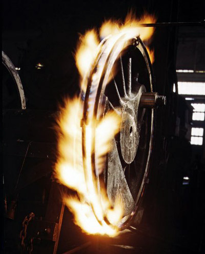
It looks like the driver he is oiling has a worn tire that should be replaced before too long. One of the tasks my grandfather performed with the Soo Line in Gladstone, MI.
Below: Re-tiring a driver wheel. Click for details.
Moving Parts
I trust all rail-fans know that there are some great videos of steamers in action on Youtube. Union Pacific 884 highballing at 75 mph:
Questions, questions
In case anyone's wondering about the dome and the pipes over the wheels, I'll point out that these are possibly the most answered questions in the history of Shorpy.
How fast can she go?
Well I've had 'er up to 55 myself.
On Shorpy:
Today’s Top 5