

Framed or unframed, desk size to sofa size, printed by us in Arizona and Alabama since 2007. Explore now.
Shorpy is funded by you. Patreon contributors get an ad-free experience.
Learn more.

- Freeze Frame
- Texas Flyer wanted
- Just a Year Too Soon
- WWII -- Replacing men with women at the railroad crossing.
- Yes, Icing
- You kids drive me nuts!
- NOT An Easy Job
- I wonder
- Just add window boxes
- Icing Platform?
- Indiana Harbor Belt abides
- Freezing haze
- Corrections (for those who care)
- C&NW at Nelson
- Fallen Flags
- A dangerous job made worse
- Water Stop
- Passenger trains have right of way over freights?
- Coal
- Never ceases to amaze me.
- Still chuggin' (in model form)
- Great shot
- Westerly Breeze
- For the men, a trapeze
- Tickled
- Sense of loneliness ...
- 2 cents
- Charm City
- What an Outrage
- Brighton Park
Print Emporium
One-Ninety: 1912
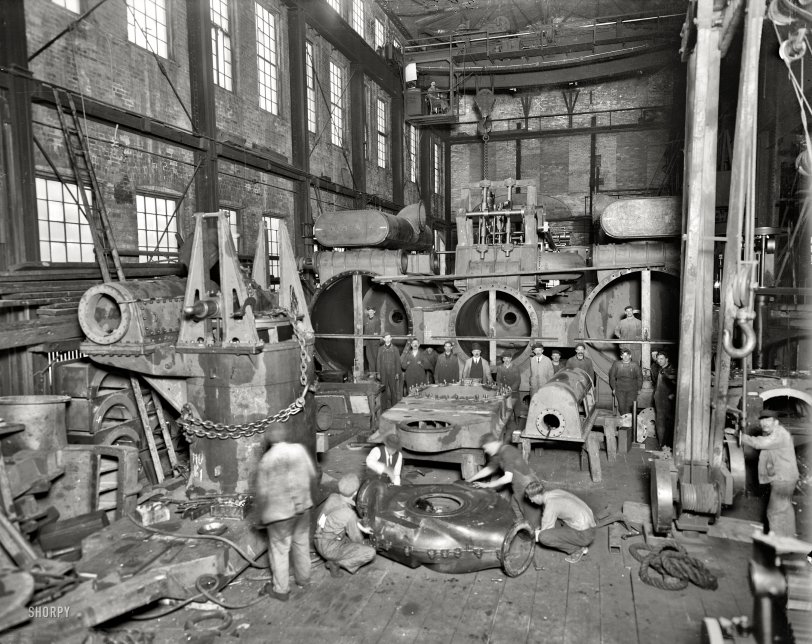
Wyandotte, Michigan, circa 1912. "Detroit Ship Building Co. Steamer No. 190, main engine in shop, three-cylinder compound-inclined type, (66 x 66 x 96) / 108 inches." 8x10 inch glass negative, Detroit Publishing Company. View full size.
Crane operator
I get a kick out of the guy sitting up in the crane. Also notably absent is any lighting.
Really big doors
Did they test run the engine in place or was it done in the ship?
Dinosaurs!
The guy with his hands tucked into the bib of his overalls gives the illusion that he has short little T-Rex arms.
One Small, Two Big
That's 66x96x96x108. No biggie!
[Not quite. Bore dimensions go in the numerator with stroke as the denominator in this notation. - Dave]

Sorry Nixiebunny
The crosses (angle iron horizontal and timber veretical) are to support centre lines (taunt wires) to allow exact alignment of components such as cylinder glands etc.
My first time post. Greetings to you all from Australian
One at a Time
It's possible to recognize some of the pieces shown here. That the engine is "3 cylinder compound" is evident. One high pressure (small) cylinder exhausts into the two larger low pressure cylinders shown behind the row of workers. (Note the class distinction: engineers wear a tie and white shirt; technicians and mechanics wear colored shirts and overalls. No one seems to be wearing a hard hat). You can see a crosshead at the left. The big pin takes the top end of the connecting rod and the guides constrain it to up and down motion only. this allows the bottom of the cylinder to have only a small hole (see it at the back end of each cylinder?) that can be sealed, allowing it to be "double acting" with a second chamber under the piston. The thing in front of the men in the middle is a cylinder head (each cylinder had a separate one in most steam engines). Above the H.P. cylinder in the background the complex mechanism seems to be part of the valve gear.
Valves were designed to be reversed, engaging a second set of cams, by moving a large lever, to allow the engine to run in reverse. No clutches, gears, or transmissions were used. The engine was sized to turn the propeller at the correct speed for hydrodynamic efficiency. Juggling the steam conditions (temperature and pressure), cylinder bores, and stroke lengths (usually the same for all cylinders) to match the hydrodynamicist's design RPM and torque for the propeller was the challenging task of the marine engineer of the time.
Shopwork!
As a retired millwright I love the insights as to how things were built back then. Not a single hand held powertool in sight, yet look what they're building.Those crosses set up in the front of the cylinders are to to keep the bore true while they wait piston installation.So much activity going on here makes me wish I was there!
Cylinder supports:
Looking closely at those cross supports you'll note the small hole in the center of the cross and a pulley just below it. A thin wire is used with this arrangement and passes through the hole at the cylinder top end and where the piston rod runs through; to another device of this type at the crank-end. A heavy weight is used to draw the wire taught. Measurements are then made to assure cylinder bore, rod and crank centers are dead in alignment as well as the wires being perfectly parallel to each other in all axis'.
Safety first?
Not one pair of safety goggles or an OSHA inspector to be seen. Despite that they all look serious enough to take their personal safety into account.
I used to live in Wyandotte, circa 1987
I see the problem
There's a small marsupial stuck in the pump housing.
Working for a Living
And not afraid to get their hands, and clothes, dirty!
Seeandbee
DSB hull number 190 was the sidewheel excursion steamer Seeandbee, launched in 1913. She later became the training aircraft carrier USS Wolverine, IX-64, operating out of Great Lakes Naval Training Center in Chicago. Many of her aircraft are scattered on the bottom of Lake Michigan.
My first guess was City Of Detroit III, but her hull number was 187.
The URL for the BGSU search page is:
http://ul.bgsu.edu/cgi-bin/xvsl2.cgi
I can waste almost as much time on that site as I do on Shorpy.
Cylinder supports
Those crosses in the open ends of the cylinders are keeping them from collapsing. How they made those cylinders back then is beyond me, although the trolley crane gives some hints as to what was possible back then, and how heavily stuff was built.













On Shorpy:
Today’s Top 5