


Framed or unframed, desk size to sofa size, printed by us in Arizona and Alabama since 2007. Explore now.
Shorpy is funded by you. Patreon contributors get an ad-free experience.
Learn more.


- Freeze Frame
- Texas Flyer wanted
- Just a Year Too Soon
- WWII -- Replacing men with women at the railroad crossing.
- Yes, Icing
- You kids drive me nuts!
- NOT An Easy Job
- I wonder
- Just add window boxes
- Icing Platform?
- Indiana Harbor Belt abides
- Freezing haze
- Corrections (for those who care)
- C&NW at Nelson
- Fallen Flags
- A dangerous job made worse
- Water Stop
- Passenger trains have right of way over freights?
- Coal
- Never ceases to amaze me.
- Still chuggin' (in model form)
- Great shot
- Westerly Breeze
- For the men, a trapeze
- Tickled
- Sense of loneliness ...
- 2 cents
- Charm City
- What an Outrage
- Brighton Park

Photos submitted by Shorpy members!
Print Emporium

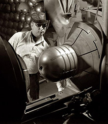


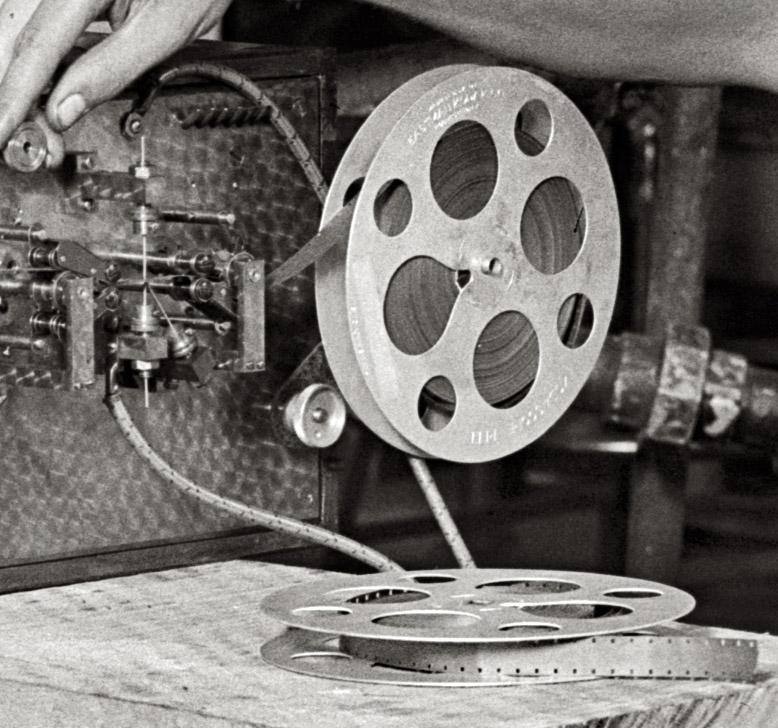
Apparatus: 1929

August 24, 1929. "Donald H. Brooks, Bureau of Standards." View full size. National Photo Company Collection glass negative. So -- what's he doing?
Testing engine power at varying humidity levels
The tape is paper. The apparatus on the left generates a high voltage spark which periodically burns holes in the paper tape. It was a brand new design in 1928 according to the NBS.
All the pipes were used to mix steam into air to get a fixed humidity for each engine test, and spark advance was changed to optimize power. Tests were at 500 rpm full throttle on a 6 cylinder ohv engine.
The resulting engineering report is available free via Google by search results "donald brooks national bureau of standards june 1929".
Earlier spark accelerometers were used by GM for fuel economy testing by fifth wheel:
https://blog.hemmings.com/index.php/2010/05/24/proven-practices/
Brooks' work was referenced right into the 1950s, and a glance at his papers shows he was a pretty technical fellow; i.e. there's a lot of advanced mathematics.
It's obvious.
His magnetic flux capacitor is being calibrated by the retroencabulator.
But the 16mm film seems to be what we used to call "full-coat" -- coated with magnetic oxide from edge to edge for sound recording.
Gasoline Testing
Gasoline quality testing measured the preignition of gasoline using this machine called an Octane Engine. Lower quality gasoline causes preignition, or "engine knock," which is measured by the vibration in the test engine. The less the engine vibrates, the higher the Octane value. Gasoline is still measured and rated in this manner today, but using a more modern engine.
Gen Set
That motor appears to be connected to a generator in back. I suspect that our intrepid researcher is measuring motor RPM against a calibrated time base to determine AC frequency.
We take it for granted now, but time and frequency were tough problems back in the electro-mechanical era. Individual generating stations were alone, unless they could synchronize their output frequency to the network. Failure to synchronize AC frequency creates heat and a loss of efficiently in transmission networks.
Oh Noes!
Whatever he's doing, he's just exposed the film rendering it all useless. Oh noes!
[Read the other comments. Whether it's exposed or not wouldn't make any difference. - Dave]
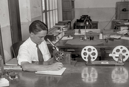
Photointerpretation
"My engine design is the smoothest and quietest made."
The Bureau of Standards was often involved in work for the patent office resolving patient claims and disputes, so testing parameters of an engine was not unusual for that time period.
The box on floor left that that looks like a tuning fork, operates much like an old doorbell. The forward coil near the weights is what drives the bars movement. The two black assemblies further up the shafts are the switches that cuts the voltage on and off to the lower coil or the electromagnet. That combination makes the two spring steel shafts oscillate back and forth and the large weights on the end limit the frequency it oscillates at to a lower speed. That assembly is powered by just one battery. It’s sole function is to “chop” or turn the DC voltage of the other battery on and off at a low fixed frequency. That chopping, turning on and off of the voltage from the other battery makes a square wave AC voltage needed to drive a transformer. In essence you could call that assembly an inverter. That principal of converting DC to AC was used up into the 1950’s and by then it was small compact unit and simply referred to as a vibrator.
That AC from the chopper box drives a transformer and is what creates the high-voltage needed for the spark gaps on the film reel assembly. The film reels and sprockets are driven by that flexible spring steel shaft coming from the geared reducer on the end of the engine crankshaft.
In the 1920,s numerous methods were tried in an effort to make talking pictures. One method was modulating a spark arcing on film to create or burn or gap of varying width that could be used with a light source and photocell. That test being performed in the photo is using a similar principle. Rather than modulate the voltage to the spark gap, the voltage and frequency to the gap is fixed. The speed of the film is varying giving a wider gap/burn at lower speed and narrow gap/burn at a higher speed. That will give a running record of the speed or smoothness of the engine. If the engine is rough running the gap on the film will be of varying widths. If the width of the burned gap is uniform, the engine will be smooth or quieter. That arrangement is simply recording the varying speed of the engine.
To reinforce testing of steady speed or smoothness of engine, note he is looking at film through a magnifying lens. His interest is not the information on the film as a whole, but rather sampling short distances at different locations on the film.
By 1929 that was old technology. Government was often slow in updating their equipment.
Shorpy, home of humor and intellect
Honestly, the amount of insightful posts on this site continues to blow me away. (And I'm certified hurricane-proof by the guvmint, so it's really hard to blow me away.) You have regular geniuses (said in earnest) teasing out the story behind pictures like this, and regular comedians (again, in earnest) making hilarious asides on the subject. This site, friends and neighbors, is why the Intarwebtubenets were/was/is/am invented.
Don't Touch That Dial
I was thinking, perhaps he was about to throw open the switches on the sonic oscillator, and step up the reactor-power input three more triangles.
Frequency Standard
The cylinders on the ends of the bars are not solenoids, they're just extra masses to reduce the frequency of the device. The actual circuit is driven by making and breaking an electric circuit that is used to excite the large wire coil in between the two bars. When the circuit is made, the coil energizes and draws the two bars in together breaking the circuit again and allowing them to spring back. The two blocks further up the bars are travel limiters to ensure both arms travel the same amount.
Self sustaining frequency standards (with pickup coils and drive coils) were a long way off then, so they had to make do with make-and-break solenoid type ones instead.
My father had a smaller one of these babies back in the late seventies in his workshop. He'd salvaged it when they threw it out of the place he worked.
The longer arm meant that a heavier mass could be used for the same frequency so it would be more stable and easier to stay in calibration. The small ones had to be calibrated against the big ones which in turn were calibrated against masters held in standards labs.
[Whew. Glad we cleared that up. - Dave]
Mr. Brooks
Gentlemen, It's clearly evident here that Mr. Brooks has discombobulated the electrostratitherm drive as a precautionary measure before threading the worm gear through the tape drive. Thereby preventing any malfunction of the tapeworm as it makes its way past the geardrive. It's as plain as the nose on his face.
[Does that titanafram look loose to you? - Dave]
That Pendulum Thing
Is probably a frequency standard. The cylinders at the near end would be solenoids that drive the tuned bars. These induce a current in an electromagnetic pickup (like a guitar pickup) and produce a very stable fixed frequency. Before fully electronic oscillators, these were widely used for precision frequency generation. The Bell system used miniatures as tone generators in the early tone-signalling system that we used to call Touch Tone. I have a couple in my junk parts bin. But those, from the 50s, are about the size of a small Sharpie.
Data acquisition
Mr. Brooks appears to be doing some kind of engine dyno work. He's probably recording performance data.
The "slab" the engine/dyno is mounted on is a tee-slot base. The tee-slots make it a nearly universal platform to work from. The top is/was machined flat and the tee-slots added. Lots of heavy machining goes into those things and their price reflects just that. Sometimes you'll see them sitting on the floor (as this one) or they can be mounted flush and built-in to the floor.
One of the batteries on the floor is 6 volts. The other one appears to be 8 volts.
What appears to be a flexible driveshaft comes off the front of the engine and (I assume) enters the back of the recorder box. For measuring RPMs? The recorder box almost looks like an old ticker tape machine.
The bar device in the box looks to me like some kind of an electrical shunt for measuring current, but it's a much more complicated shunt than I ever used.
The plumbing? Part of it cools the engine that's under test. Part of it cools the dyno brake. The built-in complexity of the contraption might have been to make it universal?
Alumni News
From the Alumni News section of Ohio State Engineer, November 1923:
Donald Brooks, '21, was one of the injured in the recent explosion at the U.S. Bureau of Standards, which was fatal to some. The men were conducting experiments on an aeroplane motor when it exploded. Mr. Brooks has fully recovered from his injuries.
The Box
If you look at the box on the ground, there seems to be huge pendulums with electrical contacts on the sides. He has that device leaning on the slab the engine is on. Then on the "recorder" device, the tape seems to go thru an arcing or vibrating styluses. My best guess is that this may be a vibration measuring device?
[The pendulum thingy looks something like a tuning fork. - Dave]
Film on reels
He couldn't be recording photographically in either of the shots as the "film" (which, from the width and sprocket pattern, certainly appears to be 16mm motion picture film in form) is completely exposed to light. Note also that the visible film appears to be completely opaque, no sign of any images. Perhaps the "recording" is being done by means of perforations, embossing or etching, and film base is being used because sprocket drive would help assure consistent speed.
[If he was doing any photographic recording on motion picture film -- recording the passage of a spark between two electrodes, for example -- he could do it in the dark, or have his apparatus covered. Or maybe it's some kind of specialized film, and the spark is so much brighter than the ambient light, it doesn't make any difference. Or it might not be photographic, if the film is being inscribed with something like a needle. Or maybe you start out with exposed film and the spark blasts away the emulsion. Or maybe ... - Dave]
Flux Capacitor 1.0
The contraption geek in me just had a stroke. So we have some great big mass of stuff on a thick concrete or forged metal slab. Some sort of inline-6 internal combustion engine. A mess of pipes and valves bordering on Three Stooges territory. I doubt the reel-to-reel is a magnetic tape recorder, since mag tape was just invented a year earlier. Or maybe it is, since it's said that the early heads were needle shaped and shredded the tape. Could it be some type of paper tape that a stylus draws on? Wish I knew what was in the big case he's leaning on. The big thingy at the left looks like the 2 counterweighted bars will vibrate at a precise rate, maybe used to calibrate something. Or maybe it's an early portable 60Hz AC inverter? I'm all atwitter.
[There were wire recorders in 1929, and devices that recorded on a thin strip of metal, but magnetic tape recorders (and magnetic tape) as we know them were still some years away. This would seem to be motion picture film. The reels are marked Eastman. Later our friend is inspecting it with a film editor. I wonder if he's using it as a kind of oscilloscope, recording a waveform or spark. Click to enlarge. - Dave]
On Shorpy:
Today’s Top 5