


Framed or unframed, desk size to sofa size, printed by us in Arizona and Alabama since 2007. Explore now.
Shorpy is funded by you. Patreon contributors get an ad-free experience.
Learn more.


- Texas Flyer wanted
- Just a Year Too Soon
- WWII -- Replacing men with women at the railroad crossing.
- Yes, Icing
- You kids drive me nuts!
- NOT An Easy Job
- I wonder
- Just add window boxes
- Icing Platform?
- Indiana Harbor Belt abides
- Freezing haze
- Corrections (for those who care)
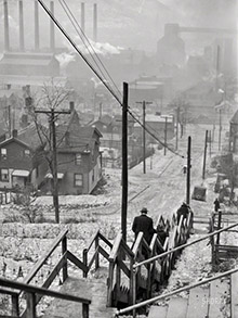
- C&NW at Nelson
- Fallen Flags
- A dangerous job made worse
- Water Stop
- Passenger trains have right of way over freights?
- Coal
- Never ceases to amaze me.
- Still chuggin' (in model form)
- Great shot
- Westerly Breeze
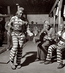
- For the men, a trapeze
- Tickled
- Sense of loneliness ...
- 2 cents
- Charm City
- What an Outrage
- Brighton Park
- Catenary Supports

Photos submitted by Shorpy members!
Print Emporium


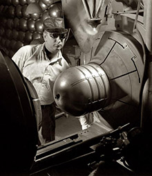


The Device: 1928

Washington, D.C., circa 1928. "NO CAPTION" is all it says here. Whatever this is, wires are involved. 4x5 inch glass negative, Harris & Ewing Collection. View full size.
What is it?
It looks like some sort of switch or distributor.
Interesting clue
Note that there are four triangular flanges over the wheel, yet on the wheel itself there are five triangular patches, presumably to block (or make) electrical contact. My guess is thus similar to JohnHoward's, that it's for advertising signage -- you get contact (and thus lights) moving forward or backward faster than the speed of the rotating disc. Think period movie palaces, with big flashing neon displays; something had to run them, and this was going to be the next big step forward.
The only thing I can say for certain
Is that thing could use a good cleaning.
It slices! It dices!
That's Ron Popeil's mother holding the device, a very early prototype of the Veg-O-Matic.
Well, clearly it's a ... a ... um ...
The triangle contactor on the upper left has a wire leaving it, which appears
to go under the glass disk to the loop and wire on the lower right, and also
to connect to the lower-right triangle contactor.
The lower left triangle similarly seems to have a wire that goes behind the board
and around to the upper-right triangle/contactor.
The metal on the glass disk at the lower left appears to have a triangular
piece of wire that sticks up to make contact with the lower-left stationary
triangle contactor.
As others have observed, they are all offset to make/break contact in sequence.
If it's for sequencing marquee lights, why did someone need to make a glass
negative of that??
[The Library of Congress archive contains thousands of photos of various inventions, gizmos and gadgets. - Dave]
Sequencer
My take on this gadget is that it's for sequencing 'traveling lights' on advertising signage.
Each of the static contact are visibly offset from the rotating contacts by different amounts so they would make and break each of the 3 (or is it 4?) circuits at different times. This would result in the illusion of motion for whatever lights were connected.
Holy Hypno!
I think the Penguin used this same device to hypnotize Batman. But in color.
Time Lord Technology
Of course it is difficult to identify as it is the variable tuning apparatus (which sits inside the control console) and is attached to the control handle for the Zig Zag Plotter on a Type 40 TARDIS.
As far as I can tell
My first guess was a device to measure the speed of light, because it looks like the one that kid on Bonanza invented for the same purpose. Except his was manually operated.
What momma used to say
"It's dirty, don't touch it!"
Whatzit?!?
Those braided or twisted leads could carry a fair amount of current, but the paperclip contact to the Device wouldn't. The glass disk hints at high voltage, and with thin pads fixed to the disk, passing between copper contacts around it, it looks a bit like a Wimshurst Machine. Note there are 5 pads on the disk, and 4 sets on the (Bakelite, I believe?) base, so pairs line up sequentially, but never all at once.
Variable capacitor?
Several good guesses already. My guess is that it's a prototype variable capacitor, such as might be used in a radio tuning circuit.
Strobe Light
You're all wrong. It's a strobe light.
Field Mill
Used to measure small static (Direct Current) charges. The rotating shutter would convert the direct current to alternating current which was more easily measured with the equipment of that time.
When trying to measure a small static charge back then, you would have major problems with drift and noise.
http://www.missioninstruments.com/pages/learning/about_fm.html
Antenna tuner/coupler ?
Could it be a variable capacitor to tune a wire antenna to a given frequency ?
Looks like it could handle a couple of kV's making it suitable for transmitting as well as receiving.
And the old advice is needed
You have to cut the blue wire first.
Seldom seen nowadays
Those of us old-timers in the graphic arts industry recognize a 1920s manual Pantone-O'Matic, which chose four complementary colors at the push of a button. Gee whiz for its day, and still in use in the mid-1960s.
Invented by Barney Day, younger brother of Benjamin Day, pressman for the old New York Sun.
The little color wheels for this device are still seen occasionally in thrift and antique shops. Folks use them to dazzle and confuse rodents and other household pests.
Not Available in Stores
It's a vegetable chopper and potato clock power source.
Ambiguous Prototype
What we have here is the first CPU heatsink prototype, redundant grounding straps and all. Either that, or a long-lost photograph of Benjamin Franklin's new-fangled lightning-kite attachment prototype.
A 1920's version of a 1830's Davenport DC motor
Looks like a teaching version of a Thomas Davenport (1802 – 1851) DC Motor. He was a Vermont blacksmith who in 1834 was credited as the inventor of the first DC electric motor in the US.
Switch for Antenna Selection?
It looks like a rotary switch with 4 postions. Not intended for significant current, so it probably is used for selecting receiving antenna for radio. Spin the glass dial to select. It is not entirely clear how the bottom triagnuar contacts are connected.
It doesn't look like a simple 1 of N selection, but could combine the antennas in certain combinations (e.g 1 + 2).
Some Kind of Motor
I wondering if the clear disk is a rotor and the four triangles mounted on the board and wired make up the stator. Science project?
Antenna switching device?
I wonder if that's an antenna switching device for radio reception. That kind of braided wire is often used for long wire antennas. It really looks like some kind of switch, but it doesn't look as if it's designed to handle much voltage or current.
Magnetic triggering device?
Just a guess, based on the clear (you can see his thumb under the wheel) circle with triangular sections blocked out with tape or something and the 4 equidistant "sensors" surrounding the rotating piece. Reminds me of a crude version of an automotive crank-triggered ignition setup.
Perhaps a Rotary Switch
This looks like a rotary switch of some sort. The disk is glass to insulate the wedges on the glass from each other. The wedges on the glass will make contact with the wedges screwed to the back plate to which the wires are attached. As the glass rotates contact will be made and broken at different times for each of the attached wires.
Presumably there is something on the back that will spin the disk, but it can't be very big as it fits in the ladies hand. Perhaps there is a shaft there that would connect to a motor.
I can't identify what it's use was. Blinking Christmas tree lights maybe; that's only a guess though.
On Shorpy:
Today’s Top 5