


Framed or unframed, desk size to sofa size, printed by us in Arizona and Alabama since 2007. Explore now.
Shorpy is funded by you. Patreon contributors get an ad-free experience.
Learn more.


- S&P
- 1940 Zenith radio model 6G601
- Quality goes in before the name goes on!
- Snazzy skirt
- Carbon Arc Lamps
- Illuminate us
- I remember it well
- I can't prove it
- Complicated then, forgotten now
- Bryan-Stevenson
- Skinny is as skinny does
- How do you rest in peace
- Riding the footboards
- Alas, hidden from view
- Baldwin Diesels
- Exclusive pump
- Bananas, Oysters and Smokey Joe
- Details, Details
- What's that building to the left of the tower?
- Coal Barges
- Bromo-Seltzer
- Inner harbor
- The Basin
- What a headache!
- Giant stepladder?
- Yeah, it was cold
- Love those coats
- Link & Pin Days Remnant
- Baldwin 62303
- Baldwin VO-1000
Photos submitted by Shorpy members!
Print Emporium


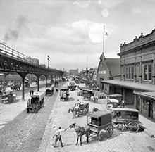

Well Connected: 1921

Washington, D.C., circa 1921. "Washington Railway & Electric Co." Harris & Ewing Collection glass negative. View full size.
Electric, not pneumatic, MU control
In all my years of researching, restoring and working on old streetcars, I've never ever encountered pneumatic multiple unit controls, only electric and these cars are no different. The jumper cables connecting the cars are for plain old "Sprague" electric MU control. Look closely at the jumper cable receptacles, you can plainly see they are for electrical connections.
Multiple Unit
These early multiple-unit systems worked off of compressed air. This allowed the motorman at the front of the trolley to control the train behind him. One set of two hoses was for the throttle control (speed) and the second set was for the reverser (forward and reverse.) Bit archaic at best, but a similar system is still in use today.
Not in DC
I think these trolleys are from Cleveland as they are equipped with dual trolly poles. The Washington DC system used a single pole system like the vast majority. In the District of Columbia there were no trolley wires allowed and power was picked up off underground conductors and sliding shoes on the trolley.
[This is not Cleveland. Washington, D.C., streetcars were equipped for both underground and overhead power supply. Overhead power was used outside the District. - Dave]
Two Answers, One Question
For Lectrogeek68:
Based on what I've seen of old electrical and phone cords, insulation back then was much thicker because of the materials used. It was cloth, jute, even paper. I had a power cord for a single light bulb that measured nearly an inch in diameter. By contrast, the trolley poles are just a pipe with no insulation. And the "clothesline" reels hold just that - rope. Nothing conductive. Good questions, now here's mine: What's with the double poles? I've seen these on trolleys in some Shorpy pix. It implies that these cars needed two overhead wires [like a trolley-bus], not a rail/ground return. I'm familiar with DC's underground plow pick-ups, but I've never seen double overhead there.
Connected, Connected With Assumptions.
I do not know alot about DC streetcars, but, it appears these two streetcars are coupled back-to-back in a streetcar 'train.'
They have two trolley poles on each car at the ends shown, and that the far trolley pole on the left car is up and on the wire?
Maybe one pole was left up inside the car barns so the car would have lights or to run the compressor. Is that a light inside above the farebox on the car to the right?
Confusing, in that I thought both poles had to be up on a two-wire system to complete the electric circuit, as the 'return' was by wire rather than the 'normal' return by the track.
( On trolley buses ( they having rubber tires ), the LEFT wire was usually the 'live' one over the centre of the track so streetcars could use it on streets with both. )
The jumper cables would be for Multiple-Unit operation and bell-signalling so the Conductor in the rear car could signal to Stop, Go Ahead, or Back Up to the Motorman in the front of the leading car.
The air brake pipe is connected thru the couplers.
I assume the trailing car received it's electricity from the leading car thru the jumper cables in this application, its trolley poles being DOWN when being used as a trailing car.
Trolley poles do not work well running backwards, a Pantograph works better as a current-collecting device in that regard.
I am assuming BOTH cars are motored and have Motorman positions at their outward ends ONLY. Each car then could be used as a single two-man car running alone on certain routes with wyes or loops, if traffic did not warrent two cars coupled.
( Here I am ASSUMING these cars had trolley poles at one end ONLY with a Motorman's position at the opposite end, only. The ends of the cars shown in the photo do NOT have headlights nor route signs and were intended to run coupled as built??
But the car on the right has a 'people catcher' under the step, actuated by the horizontal crossbar beneath the couplers, and, I am assuming the car on the left has one, too? )
There would be a Motorman and Conductor on the front car and a lone Conductor on the rear car, saving one wage operating two cars coupled.
Doors to enter/exit on the far side can be seen thru the open doors of the car on the left, and on the car on the right.
Possibly the two-car set just changed ends at the termini, the Motorman travelling to the far end of the trailing car on arrival, lowering the trolley poles on the incoming front car and raising the trolleys on the new front car for departure, the respective Conductors staying at their locations?
The cars then would use a crossover to cross onto the right hand track to return to the opposite terminus?
This would eliminate a wye or a turning loop.
I do not know the procedure of turning streetcars and trains in DC.
It would be nice to see another photo of these two cars out on the road illustrating their fronts and the two trolley wires.
In later years many DC cars ran with the ( single ) trolley pole down in the city core, receiving their electricity from a conduit in the centre of the track.
Another great photo from Shorpy showning just how much I need to learn regarding streetcars years after their demise.
Thank You, Sir!
Plumbing matters
I looked at the S Trap Lectrogeek68 mentioned & I think it's an odd bit of drainage, the lack of rodding access & no other branch lines entering into the stack make me think it my be a trapped combined storm water sewer system collecting a box gutter or pavement drain the trap stopping miasma gases
There's not even an inspection gate at the stack base.
MU
To answer a couple of questions posed by Lectrogeek68, the cables connecting the cars are for Multiple Unit control, by which the motorman in the lead car can operate the motors in both cars simultaneously. This system was the norm on subway/elevated lines, but less common on street railways. Each cable carries several conductors. The air brake connections are next to the couplers.
As for the "clothesline", the trolley rope which connected the pole to the retriever was indeed just a piece of rope, so insulation from the 600 volts was not an issue (though I would be hesitant to handle it in a rainstorm).
Cables and rope
Part of the reason the cables between the cars seem bigger than the trolley poles for collecting electricity from the overhead wires is the insulation. Flexing is another reason for thick wires, the pole doesn't have to bend back and forth without breaking. As for the "clothesline" rope, it's not wire rope, but some plant matter that is naturally insulating.
Some Technical Trolley Answers
The trolley rope is most like;y "Samson Spotcord," which was a type of rope usually used for window sashes which I believe is made of cotton so it would not conduct electricity. The power was actually conducted from the trolley wheel down the trolley pole to the trolley base (not shown in this picture) and then wired into the car. I had forgotten that certain Washington area trolley lines had double wire overhead, one for positive and one for ground. Most trolley systems used the actual running rails for ground. Even the conduit system in the District of Columbia proper had two contacts in the slot, one positive and the other negative for ground and did not use the running rails as a return except on the few lines that went over the DC boundary line. There they had a men in pits who removed the conduit plow and threw knife switches under the car to change over to the more typical trolley pole positive and rail negative.
These two streetcars are coupled together in MU or Multiple Unit operation. In this mode only one man was needed to motor the "train" and a two conductors, one for each car to open doors, collect the fares and issue transfers, saving labor costs when high capacity service was needed. Toronto, Canada (is) was the last North American streetcar system to use this system with conventional streetcars. San Francisco MUNI does this with more modern LRV style cars today but I don't believe did it with more conventional cars such as these. The electrical cables connect the control and signal systems between the two cars which could be operated individually when capacity was not needed. There is also an air brake line next to the couplers that make the actual mechanical connection between the two units. This certainly is a fascinating picture showing many of the details of this not so common type of streetcar operation.
Mechanicals
Down by the couplers are the two hoses providing compressed air to power and operate the brakes. The four electric cables look large due to insulation. While not familiar with the control system I'd speculate the cables provide a "multiple unit" connection whereby a motorman in a lead car can operate the trailing car as well. Note that the car on the left has but one trolley pole while the right has two. Later cars dispensed with the wheel (trolley) on the pole and used shoes but the name stuck.
Details
I agree with Switzarch. The comments and Dave's titles always entice me into combing over every square inch so as not to miss a detail. Sometimes, at a glance, I'll think a photo has nothing of interest to me. I should know better. This was just such a photo. I glanced and moved on.
Shoes
I thought maybe he was commenting about the wrong picture. You know, maybe the "lone shoe" in a few pictures back. Thanks for clarifying.
Fare Box
Visible in the second car is a Johnson type D cranker fare box. The passengers would drop their fare in the top of the box and after the stop the conductor would push a lever which would send the collected coins to the counter. The conductor would then rotate the crank until all the coins were counted. At the end of the shift the money turned in would have to match the difference of the counters from the previous shift.
Did you read about the fire at the Shoe Factory?
I'll bet some heel started it.
Easter egg hunt
I couldn't agree more with "switzarch" - many of the user comments are like an Easter egg hunt - of cultural minutiae. A delightful, and sometimes informative, adventure.
Less Was More
There was an elegance in simplicity to some of these older pictures of technology.
Couple Things
Thoughts that pop randomly into my admittedly geeky brain:
1. The beefy size of the interconnection cables, relative to the trolley pole itself.
2. How exactly is the "clothesline" that reels in the trolley pole insulated for 600 volts (give or take)?
3. The S-trap on the wall, without vent, which may possibly have met plumbing codes at the time.
4. How many tuberculosis bacilli must be thriving on the pavement?
Hey, with only one advertising sign, and no people, what else are you going to comment on?
Details
"Walt" show again why these photos are so interesting. I read his comment and couldn't figure out what prompted it then I 'full sized' the picture and had to search about. He saw that advert inside the car. Wonderful. It's fun when a comment is made about something almost invisible. Great fun, thanks, Walt. Much appreciated.
O'Sullivan's Heels
The first rubber heel for shoes was patented on January 24, 1899 by Irish-American Humphrey O'Sullivan. O'Sullivan patented the rubber heel which outlasted the leather heel then in use. Elijah McCoy invented an improvement to the rubber heel.
On Shorpy:
Today’s Top 5