


Framed or unframed, desk size to sofa size, printed by us in Arizona and Alabama since 2007. Explore now.
Shorpy is funded by you. Patreon contributors get an ad-free experience.
Learn more.


- Details, Details
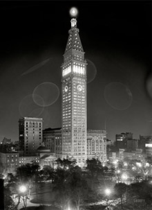
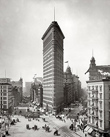
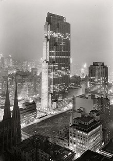
- What's that building to the left of the tower?
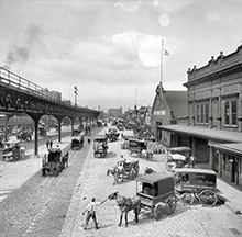
- Coal Barges
- Bromo-Seltzer
- Inner harbor
- The Basin
- What a headache!
- Giant stepladder?
- Baldwin 62303
- Baldwin VO-1000
- Cold
- No expense spared
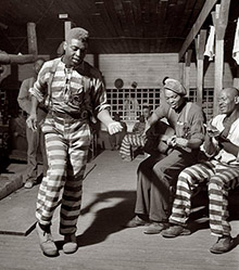
- Tough Guys
- Lost in Toyland
- And without gloves
- If I were a blindfolded time traveler
- Smoke Consumer Also Cooks
- Oh that stove!
- Possibly still there?
- What?!?
- $100 Reward
- Freeze Frame
- Texas Flyer wanted
- Just a Year Too Soon
- WWII -- Replacing men with women at the railroad crossing.
- Yes, Icing
- You kids drive me nuts!
- NOT An Easy Job
- I wonder
- Just add window boxes

Photos submitted by Shorpy members!
Print Emporium


The Blacksmiths: 1904

Despatch, New York, circa 1904. "Blacksmith shop, Merchants' Despatch Transportation Co." Operations of the refrigerated rail freight line in what is now East Rochester. Panorama of two 8x10 glass negatives. View full size.
Thanks for the help!
Thanks to everyone for the information on the machines shown here. (I'm working on a model of a turn-of-the-last-century machine shop and this really helps me understand what I'm trying to replicate.)
Twins
A two photo panorama like this make me imagine - Wouldn't it have been fun to tell all the guys on the left to move to positions on the right before the second shot was taken?
Ok yeah - it would have disrupted the documentary nature of the picture. I guess that is why I couldn't be a documentary photographer.
Questions Answered
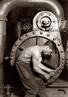
The handles extending forward from the press control the clutch. This particular model has a bar with handles on each side, to allow operation from either side. The bulldozers we had in the shop where I worked were notorious for being difficult to disengage, and were generally run continuously engaged. The cycle speed was very slow, about 15 seconds for a complete cycle, so you had plenty of time to remove the finished piece and place a new blank during the cycle without disengaging the clutch.
The dies determined how many "hits" were required for each piece. The simple dies shown were likely all designed for one cycle to complete the operation. The machines in our shop were used mostly with "puzzle" dies, where multiple bending and forming operations were possible, depending where in the die the piece was placed.
I made a great many uncoupling levers (pin lifters) in a machine just like this. Starting with a round bar that had already been sheared to length, one end was put into one section of the die where the "U" bend was started. Next cycle, the partially bent "U" was placed in another part of the die where the "U" was finished. Then the rod with the "U" on the end was laid in yet another part of the die, where both offsets were formed, then turned and put into yet another area of the die where the 90 degree bend for the handle was made, and finally stood upright into the last portion of the die where the handle was formed.
2 minutes were allowed for each finished part, 30 per hour. The danger was letting your mind wander and putting your hand in the wrong place at he wrong time.

Multiple Passes
Machines like that have a ratchet mechanism. Push the handle; the machine does one stroke, then stops, even though the power input is still turning. The one on our big shear needs cleaning, oiling, and adjustment, because it does multiple strokes. If we used it a lot we'd fix it.
When it's unbelted and there's nothing in the dies, it's pretty easy to turn. Die fit is checked and adjusted by unbelting, tripping the actuator, and turning the input wheel by hand.
Multiple strokes are a matter of terminology. If it's meant to do the full job in one stroke it's a "press". If it's set to do multiple strokes to get to the final shape, it's a "hammer". That isn't exact, and there are exceptions both ways.
Belts
This picture clearly illustrates how factories used to power their machines: thick belts are attached to a rotating shaft near the ceiling, the shaft most likely being powered by a steam engine.
Forge Questions
So what is that horizontal handle extending forward from the press? I'm guessing some sort of clutch to disengage the power but the man obscures the details of the machinery.
Also, would a piece be formed with one press of the forge or would multiple cycles of the gear be needed for the final product?
Manual die set ups
In looking at the belt driven bulldozer, I was wondering how the would check the draw on the dies for proper fit to avoid damage before belting up the machine. Then I saw the holes placed in the pinion gears and long rods in the can to the left. That's my guess anyhow.
Horizontal Forging Press
Henley's Encyclopedia of Practical Engineering
and Allied Trades, 1906.Horizontal Presses.
29. Bulldozers.— The bulldozer is a horizontal press for performing bending, forging, and welding operations. In the illustration, a pair of dies a, b is shown in position for bending the piece of work f. The movable die b is attached to the ram d which is driven by the connecting-rods c,c. These machines are made to be driven by a belt, engine, or electric motor, and are used for a very large variety of work, especially for such work as the forgings for car trucks, for agricultural implements, etc. An almost endless variety of work can be done on them, including forging and welding. The stock is generally put in the dies hot …
This model appears to be manufactured by Williams, White and Co., of Moline, Illinois.

The Bulldozer
The machine in the left foreground is a "Bulldozer", a very handy machine for repetitive tasks. The big crank arms on each side are connected to the "ram", which slowly advances & retracts. It is a sort of horizontal press. The dies for the machine are to the right in a pile on the floor. Slightly to the right of the "Bulldozer" and in the background is a double-ended Whitney press. These were used as punching machines, bar cutters, etc, depending on the dies installed. The hammer in the middle distance is not a steam hammer. It is a "Bradley" trip hammer, operating off the shafting. It has a wooden arm with a hammer shoe on the end, and the crew is making (or repairing) a bottom rod for brakes.
This is a common layout for a RR blacksmith shop. They would have made mostly things like grab irons, uncoupling levers, sill steps, handholds, light truck and brake parts, etc. I worked in a shop that included all of the machinery shown here (and lots more of the same or earlier vintage) in the 1970's.
Staring intently.
He is weighing something on a scale. The machine on the left is a forming press rather than a hammer. There are other forming dies piled to the right of it.
Press Here
The machine on the left is a press. If you look. closely, you can see the die that have formed the piece that the two men are removing. There are more dies, to the right, that are used to form other parts.
Machinery
Anyone know what that machine on the left does? Since the two gents are handling that piece of an arch-bar truck with tongs, I'm guessing it's been heated which would make this some sort of forging hammer. Maybe it's a riveting machine of some sort?
There's a steam hammer in the middle distance on the right and a forge for heating the rivets on the far right. The cart in the center is piled with more rivets. And there's this one guy in foreground staring intently at some contraption with a handle and a couple of rollers on it, whose purpose also escapes me.
But lots of belts and pulleys. With the hammering and riveting, this must have been a very noisy place Back In The Day.
Clang, clang, clang
Clang, clang, clang went those sledge hammers. Must have made a terrible racket on iron and steel and with no hearing protection. That's the way real men did it! "Eh - what's that ya say"?!
On Shorpy:
Today’s Top 5