


Framed or unframed, desk size to sofa size, printed by us in Arizona and Alabama since 2007. Explore now.
Shorpy is funded by you. Patreon contributors get an ad-free experience.
Learn more.


- Baldwin 62303
- Baldwin VO-1000
- Cold
- No expense spared
- Tough Guys
- Lost in Toyland
- And without gloves
- If I were a blindfolded time traveler
- Smoke Consumer Also Cooks
- Oh that stove!
- Possibly still there?
- What?!?
- $100 Reward
- Freeze Frame
- Texas Flyer wanted
- Just a Year Too Soon
- WWII -- Replacing men with women at the railroad crossing.
- Yes, Icing
- You kids drive me nuts!
- NOT An Easy Job
- I wonder
- Just add window boxes
- Icing Platform?
- Indiana Harbor Belt abides
- Freezing haze
- Corrections (for those who care)
- C&NW at Nelson
- Fallen Flags
- A dangerous job made worse
- Water Stop

Photos submitted by Shorpy members!
Print Emporium


Mystery Coach: 1910

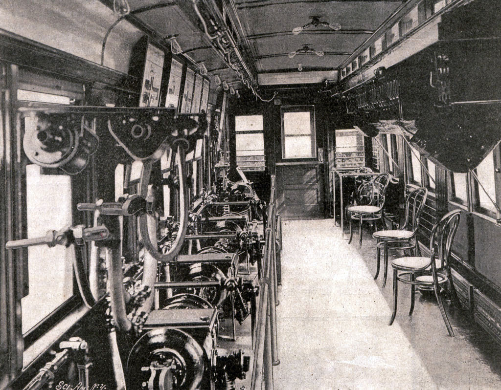
From around 1910 comes this 5x7 glass negative showing a rail car fitted with ... what? Post your informed supposition in the comments. View full size.
Sister Cars
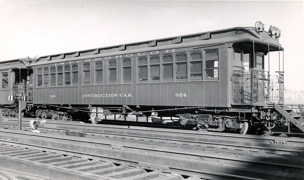
A pair of lovingly preserved (but more conventional) ex-IRT coaches are at home at the Western Railway Museum at Rio Vista Jct. (Suisun City/Fairfield, California). In their "last gasp" service lives, the were WWII-era "Shipyard Railway" cars running between East Bay (Berkeley, Oakland and Richmond) communities hauling war-workers.
Car 824, no doubt
It is indeed the interior of IRT Instruction Car 824 - you can barely make out '824' right over the door. I've been in this car - it's at the trolley museum in Branford, Connecticut.

I See the Light
Maybe the light bulbs came on in a sequence from left to right or right to left to indicate how the brakes engaged in a sequence? Or perhaps they indicated the cleanness and accuracy of the shot of tobacco juice aimed at the spittoon?
You're all wrong.
It's the inside of a TARDIS.
Controller size
is indeed small. To amplify comments from Railroad_Sparky and SteveLexington, streetcar controllers actually controlled the motors directly, and so had to carry the 600 volts (or so) and the heavy motor currents. Thus, the contactors inside the controller had to be large to carry the large currents, and had to have large separation to extinguish the high voltage arc (spark).
"Multiple Unit" (MU) control was introduced to allow one motorman to control several cars (multiple units) from one controller at the front of the train. Air brakes had been developed already to do this for the brakes, but it took a while longer to control this mysterious 'electricity'. MU controls typically used low voltage control circuits. These were coupled between cars using a multi conductor (7? 14?) plug-in cable. The low voltage would operate heavy duty contactors on each car, which in turn controlled the traction current and voltage. Since the current and voltage are both (relatively) small, a controller can be made much smaller.
Mobile Hot-Spot
This one was easy. You've got your bank of Wi-Fi routers and access points on the left, and your uninterruptible power supplies on the right. Looks like they've opted for the air-cooling option center-right.
New York Is On The Move!
IRT Instruction Car
This looks like the New York Subway (IRT) instruction car.
There are slight differences between the two cars pictured but this could be due to modifications over the years, or possibly there was more than one instruction car in the fleet.
Railroad_Sparky is right that the controller appears small. Streetcar controllers usually had bigger cabinets but this one is actually pretty typical of multiple-unit controllers used in rapid transit cars.
Just an observation
It seems that every "break unit" on the right is separated by flexible line like between cars and there's a small reservoir like what would be much larger under each coach car. So I think this might be a mechanical model of a train of coaches to demonstrate what? Same with the electrics on the left with all the electric heater units that are all over the break side also.
[Another observation: BRAKE, not "break." - Dave]
Thanks Dave. I'll never screw up there their they're but otherwise we're free ranging.
Instruction Car.
Yes, this most certainly is an instruction car and there are several interesting features: The metal boxes on the left wall next to the floor are electric heaters - as are the same on the right. The cylinder with the arm attached, above, is most certainly a carbon-pile Voltage regulator. The white things I suppose are insulators. The seven glass tubes on the wall I suspect are load or indicator lamps. Hard to tell if this was a 32-Volt (steam line) car or an electric line (600+ Volt) car.
The very curious thing about both sides is the standee straps - guess part of the instruction was carried out while the car was moving.
It appears that this was an open-platform car (looking through the windows).
Another curious feature is the controller to the right of the door. It does not appear to be an engineer's/motorman's brake stand - but could be - maybe. It is too small to control traction motors. Moving around the right side, yes, those are most certainly K Brakes. Have considerable Westinghouse, Pullman, etc. reference material on this era equipment. Note the framed posters above each station. These appear to be valve air channel diagrams. But in addition to the other curiosities, it seems odd that there are no air pressure gauges included with the stations.
Certainly Instruction
The equipment on the right side is railroad brake equipment, as deemery said. There is equipment for several cars, so the propagation of the braking commands can be seen.
The equipment on the left is for propulsion control for (as Pudgyv said) an interurban or transit car. On the left, in the foreground (and a bit out of focus) is a jumper connection, used between cars for multiple unit control. The equipment hanging from the ceiling seems to be contactors for motor control. The metal housings near the floor are heaters which may serve as resistors to limit motor current for low speed/slow acceleration. The white "pipes" between the contactors and the floor may be cables between the contactors and the motors mounted on the trucks below the floor. I suspect the white stuff is asbestos insulation; these cables would carry the traction current at around 600 to 750 volts, and hundreds of amps.
Another track
Those may well be air brake assemblies but I suspect they're doing other work, the labeled electrical gear with hefty looking trunking on the opposite side argues against this being a very mobile installation even if the motorman's station is still in place, what we can see of those display boards above the pneumatic gear looks rather maplike.
All this added together with the seven bulb light board, the desk, chair, and spittoon leads me to suspect we are looking at an interurban car repurposed as a switch and signal house either in a small hump yard or on a factory premises.
Instructions
Part of the instruction could be how to hit the spittoon. The whisk broom is a nice, dainty touch. So are the hanger straps.
My guess is that it's a transit car converted hastily to a dynamometer car, with plenty of heavy wiring and large resistors to dissipate heat. My dad worked on one in the late '30s to test diesel locomotives for the Milwaukee Road.
Motorman's Instruction Car
And the Answer Is ...
... I don't know for sure. But I have a hunch. And I think braking is (so to speak) on the wrong track. Maybe the rectangular objects, radiator-like fixtures and light bulbs on the left are clues.
You Brake It
I'm going to guess this is an Air Brake Instruction Car.
I know such cars existed, I've seen references to them on various RR rosters. The contraptions on the right hand side are brake cylinders (air reservoirs and triple valve, Westinghouse K or equivalent.)
The problem with my guess is I can't directly account for the electrical stuff on the left side.
Instruction car.
I'm assuming that this is an instruction car for either an interurban railway or an elevated transit line. In either case you can see the master controller just to the right of the end door. Along the right side is a bank of air compressors while above those are what look like framed study guides or instructions.
Edit, after reading the other post I have to agree. Along the right side are are brake cylinders.
On Shorpy:
Today’s Top 5