


Framed or unframed, desk size to sofa size, printed by us in Arizona and Alabama since 2007. Explore now.
Shorpy is funded by you. Patreon contributors get an ad-free experience.
Learn more.


- Baldwin 62303
- Baldwin VO-1000
- Cold
- No expense spared
- Tough Guys
- Lost in Toyland
- And without gloves
- If I were a blindfolded time traveler
- Smoke Consumer Also Cooks
- Oh that stove!
- Possibly still there?
- What?!?
- $100 Reward
- Freeze Frame
- Texas Flyer wanted
- Just a Year Too Soon
- WWII -- Replacing men with women at the railroad crossing.
- Yes, Icing
- You kids drive me nuts!
- NOT An Easy Job
- I wonder
- Just add window boxes
- Icing Platform?
- Indiana Harbor Belt abides
- Freezing haze
- Corrections (for those who care)
- C&NW at Nelson
- Fallen Flags
- A dangerous job made worse
- Water Stop

Photos submitted by Shorpy members!
Print Emporium


Throwing the Switch: 1929

February 27, 1929. Washington, D.C. "Testing installation for radio broadcast of the Inauguration." On the eve of the Great Depression, a sound check for the presidency of Herbert Hoover. National Photo Co. View full size.
Some more comments
A few comments on the identifiable components: The amplifiers in the upper portion of each of the four cabinets are Western Electric 8A amplifiers. These are three stage amplifiers that were developed for public address work and later were used in broadcasting for transmission over lines or to drive a radio transmitter (later revised and improved with the 8B and 8C variants). The 8A used two type 102D tubes and a single 205D tube. The input impedance is 200 ohms (two 100 ohm carbon buttons on a double button microphone) and the output impedence is 500 ohms. The amplifiers include three rheostats to control the filament current for the tubes and the button current for a carbon microphone. As stated in one of the previous comments, this rheostat is marked "transmitter current". Western electric referred to these microphones as transmitters. The central knob that the seated man has his hand on is the input attenuator. On the upper left of each amplifier there are a series of jacks for checking transmitter button current, filament currents and plate currents for the tubes.In the right hand portable case, there is a 514A meter panel that was used to monitor currents. It consists of a panel with three weston type 267 meters mounted on it. 100 milliamperes, 10 milliamperes and 4 amperes. Below the meter panel in that case, there is mounted a Western Electric 518 "VU" meter panel. It is the unit with two square rheostats side by side in the center with a meter to the left. I can not identify the panel below the VU meter. Nor can I identify the panels in the lower parts of the other three cases.
Equipment
Top row are probably microphone amplifiers (it's a pretty common Western Electric amp of the period and output from a carbon microphone is at a pretty high level), appears to be a mixer at lower left and another partially obscured by the chap in eyeglasses. Not sure about the gadget to the right of that.
We're used to teeny-weeny terminal equipment but at the time, that was about as small as the high-end "pro" stuff got, especially when set up for redundancy as they did (and still do) for an important event like an Inauguration.
This lash-up would have sent the audio signal to various transmitters via (dedicated) telephone lines, likely indirectly via the very new radio network(s) to individual stations. NBC wasn't quite three years old at the time and CBS was barely two, depending on when you count from.
Audio Gear
I do not see anything there but audio gear. Each module has quarter-inch jacks which were used for patching telephone connections (think of the old time operator switchboards).
They probably would end up mounting a microphone for each of the (apparent) 4 amplifiers (with room for 2 more).
The narrow cabinets do not hint at all of the bulky RF transmitter gear that would be in use in that era. RF equipment would not be in shiny metal enclosures, for sure.
This is the patchboard end of telephone lines running some distance to the transmitter sites, perhaps across country to New York, Chicago and the West Coast.
There is one knob that seems to be labelled "transmitter" but that term is used for telephone lines as well as radio.
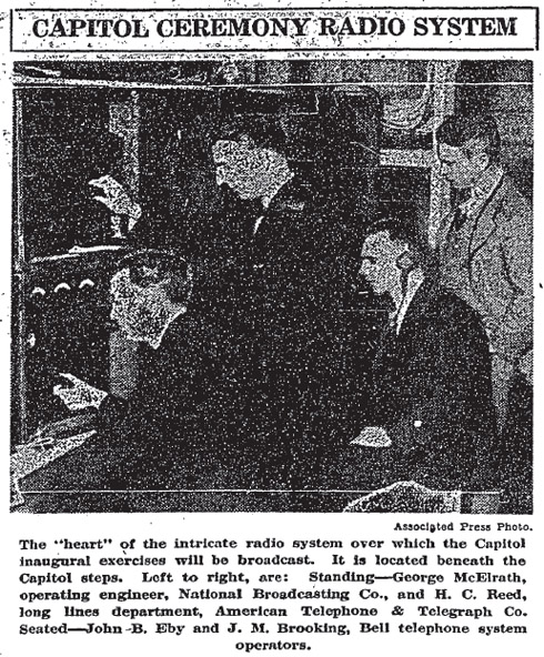
The AP photo Dave added reinforces this idea as it identifies telephone company personnel.
1920s transmitters
This was before the era of plate modulation. In those days the modulation was applied to a low level stage -- typically soon after the oscillator then followed by linear amplifiers. The fact that there are two tubes doesn't necessarily indicate push-pull since it was common in those days to operate tubes in parallel.
1920's radio gear
This looks like a dual portable transmitter setup. Those are microphones being attached with springs to the stand. Note the array of batteries under the table; in the pre-transistor world, vacuum tube amplifiers required very high voltages (200-400V) for the plate voltage supply.
These batteries were strung together in series to get the large voltages needed.
The upper half of each case appears to be either the RF output stage or modulator stage; in an AM transmitter both are usually large push-pull stages as indicated by the twin tubes in front of the guy's glasses. He's probably adjusting an attenuator or tuning circuit to maximize transmitter output.
The dawn of electronics
The equipment is well built and of professional caliber. Yet it's strangely primitive. There are only two vacuum tubes installed at the time the photo was taken. They were probably packed separately to avoid breakage.
There are rheostats for each filament, labeled "FILAMENT n". That's not a feature that survived the thirties.
The huge pile of batteries on the lower shelf was needed to provide power before rectifiers became commonplace. That row of knife switches on the left end of the table was probably used to switch the batteries on. They're not wired up yet. It looks like hours of site work was needed to prepare this equipment for use!
All in all, a marvelous portrait of the state of the art.
On Shorpy:
Today’s Top 5